CNC Press Brake Bending: A Fabricator’s Fundamentals
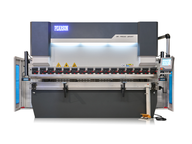
CNC press brake bending forms sheet metal by pressing it between a punch and die under controlled force, with the CNC system managing ram depth, speed and back gauge position to produce accurate, repeatable bends. Understanding how the process works helps you programme faster, reduce scrap and get consistent parts from the first piece.
This covers the core principles every fabricator working with a CNC press brake needs to understand: how bends form, what causes inaccuracy and how to control the variables that matter most.
How a CNC Press Brake Forms a Bend
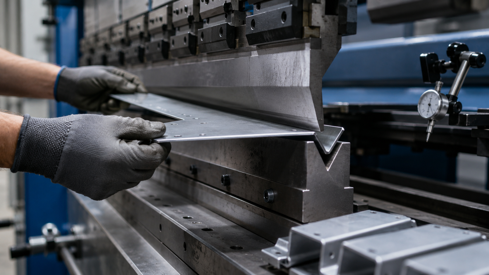
The punch descends into the die, forcing the sheet metal to conform to the gap between them. The CNC controller dictates exactly how far the ram travels, which determines the bend angle. The back gauge positions the sheet so each bend lands in the right place.
Three things define the result: the tonnage applied, the depth of the punch stroke and the geometry of the tooling. Get all three right and you get a consistent bend. Get any one wrong and the part comes out inaccurate, or the tooling takes damage.
Air Bending vs Bottom Bending vs Coining
These are the three main bending methods. Each uses different amounts of force and produces different results.
| Method | Force required | Angle control | Best for |
|---|---|---|---|
| Air bending | Low (partial contact) | Controlled by ram depth | General work, multiple angles |
| Bottom bending | Medium-high (full contact) | Controlled by die angle | Consistent angles on repeat runs |
| Coining | Very high | Controlled by tonnage | High-precision work, minimal spring-back |
Air bending is the most common method in modern CNC press brake bending because it offers flexibility. You can produce a range of angles from a single V-die by adjusting the ram depth. It also requires the least tonnage, which reduces wear on tooling and machine.
Bottom bending and coining sacrifice that flexibility for precision. Coining virtually eliminates spring-back but demands significantly more force, which means higher tonnage machines and heavier tooling.
Bend Allowance: Why Flat Patterns Do Not Match Finished Dimensions
When metal bends, the outer surface stretches and the inner surface compresses. The neutral axis, the line inside the material that neither stretches nor compresses, shifts toward the inside of the bend. This means the finished part is slightly longer than the sum of its flat dimensions.
Bend allowance accounts for this. It calculates how much material is consumed by the bend itself, based on material thickness, bend angle, inside radius and the K-factor (the position of the neutral axis relative to thickness).
If your flat pattern does not include correct bend allowance calculations, the finished part will be the wrong size. Most CNC controllers handle this automatically once you input the material parameters, but understanding why it matters helps you catch errors before they reach the shop floor.
Spring-Back and How the CNC Compensates
Every material springs back slightly after bending. Mild steel might spring back 1-3 degrees. Stainless steel and aluminium spring back more. The exact amount depends on material grade, thickness, grain direction and bend radius.
CNC press brakes compensate by over-bending: if the target angle is 90 degrees and the material springs back 2 degrees, the controller pushes the ram to 88 degrees. Modern systems measure and adjust this automatically across a run, refining the compensation as they go.
Where spring-back causes problems is when operators assume the programmed angle equals the finished angle without accounting for material variation. Different batches of the same grade can behave differently. Running a test bend on each new batch avoids cumulative errors across a production run.
Tooling Selection for CNC Bending
The tooling you choose affects bend quality, machine longevity and what shapes you can produce.
The die V-opening should typically be six to eight times the material thickness for air bending. Too narrow and the tonnage spikes. Too wide and the inside radius becomes too large for the application.
Punch selection depends on the bend profile. Standard punches handle most right-angle work. Gooseneck punches provide clearance for return flanges. Acute punches handle tight angles. Radius punches produce curved bends rather than sharp folds.
For workshops running mixed jobs, segmented tooling offers the most flexibility. Segments can be rearranged to match different bed lengths without changing the full tool set.
What Causes Inaccurate Bends
Most bending inaccuracy traces back to one of four things: incorrect material data in the programme, worn or mismatched tooling, inconsistent material thickness between batches, or a back gauge that needs recalibrating.
Before troubleshooting the machine, check the basics. Verify the material grade and thickness match what the programme expects. Confirm the die width suits the material. Run a test bend and measure with a calibrated protractor or angle gauge.
If accuracy problems persist after setup checks, AFM’s support and servicing team can assess calibration, back gauge alignment and ram repeatability on both new and used press brakes.
For guidance on choosing the right machine for your bending requirements, contact AFM’s press brake team to discuss tonnage, bed length and control specifications for your workshop.